After completing this unit, the student should be
able to:
• Identify the classes (lớp) of jigs and fixtures (fixtures).
• Identify the types (loại) of jigs and fixtures (fixtures).
• Choose a class and type of jig and fixture for
selected operations on sample parts.
JIGS AND FIXTURES(fixtures)
Jigs and fixtures (fixtures) are production-workholding devices
used to manufacture duplicate parts accurately. The
correct relationship and alignment between the cutter,
or other tool, and the workpiece must be maintained.
To do this, a jig or fixture is designed and built to hold,
support, and locate every part to ensure that each is
drilled or machined within the specified limits.
Jigs and fixtures (fixtures) are so closely related that the
terms are sometimes confused or used interchangeably.
The difference is in the way the tool is guided to the
workpiece.
A jig is a special device that holds, supports, or is
placed on a part to be machined. It is a production
tool made so that it not only locates and holds the
workpiece but also guides the cutting tool as the operation
is performed. Jigs are usually fitted with hardened
steel bushings for guiding drills or other cutting
tools (Figure 2–1A).
As a rule, small jigs are not fastened to the drill
press table. If, however, holes above .25 inch in diameter
are to be drilled, it is usually necessary to fasten
the jig to the table securely.
A fixture is a production tool that locates, holds,
and supports the work securely so the required
machining operations can be performed. Set blocks
and feeler or thickness gauges are used with fixtures (fixtures)
to reference the cutter to the workpiece (Figure 2–1B).
A fixture should be securely fastened to the table of
the machine upon which the work is done. Though
largely used on milling machines, fixtures (fixtures) are also
designed to hold work for various operations on most
of the standard machine tools.
Fixtures (fixtures) vary in design from relatively simple
tools to expensive, complicated devices. Fixtures (fixtures) also
help to simplify metalworking operations performed
on special equipment.
CLASSES OF JIGS
Jigs may be divided into two general classes: boring
jigs and drill jigs. Boring jigs are used to bore holes
that either are too large to drill or must be made an
odd size (Figure 2–2). Drill jigs are used to drill,ream, tap, chamfer, counterbore, countersink, reverse
spotface, or reverse countersink (Figure 2–3). The
basic jig is almost the same for either machining operation.
The only difference is in the size of the bushings
used.

Drill jigs may be divided into two general types, open
and closed. Open jigs are for simple operations where
work is done on only one side of the part. Closed, or
box, jigs are used for parts that must be machined on
more than one side. The names used to identify these
jigs refer to how the tool is built.
Template jigs are normally used for accuracy rather
than speed. This type of jig fits over, on, or into the work
and is not usually clamped (Figure 2–4). Templates are
the least expensive and simplest type of jig to use. They
may or may not have bushings. When bushings are not
used, the whole jig plate is normally hardened.


Plate jigs are similar to templates (Figure 2–5).
The only difference is that plate jigs have built-in
clamps to hold the work. These jigs can also be made
with or without bushings, depending on the number
of parts to be made. Plate jigs are sometimes made
with legs to raise the jig off the table for large work.
This style is called a table jig (Figure 2–6).
Sandwich jigs are a form of plate jig with a back
plate (Figure 2–7). This type of jig is ideal for thin or
soft parts that could bend or warp in another style of
jig. Here again, the use of bushings is determined by
the number of parts to be made.
Angle-plate jigs are used to hold parts that are
machined at right angles to their mounting locators
(Figure 2–8). Pulleys, collars, and gears are some of
the parts that use this type of jig. A variation is the
modified angle-plate jig, which is used for machining
angles other than 90 degrees (Figure 2–9). Both of
these examples have clearance problems with the cutting
tool. As the drill exits the product being drilled,
it has little or no room for the drill point to clear the
product completely, produce a round hole all the way
through the part wall, and avoid drilling the part locator.


This is most noticeable in Figure 2–9, where an
angled hole requires additional clearance to the
relieved portion of the part locator. Additional clearance
here would allow the drill to complete the hole
and avoid drilling the relieved portion of the locator.
The part locator will most likely be hardened and the drill will be lost as a result of any attempted drilling.
Additional clearance on the relieved diameter of the
part locator may be possible. A larger clearance hole
in the locator could also be added if the relieved
diameter cannot be reduced. The additional design
consideration added to the locator would include the
feature to provide the correct orientation of this clearance
hole or machined relief to line up with the bushing
location.
Box jigs, or tumble jigs, usually totally surround
the part (Figure 2–10). This style of jig allows the
part to be completely machined on every surface
without the need to reposition the work in the jig.
Channel jigs are the simplest form of box jig (Figure
2–11). The work is held between two sides and
machined from the third side. In some cases, where jig
feet are used, the work can be machined on three sides.
Leaf jigs are small box jigs with a hinged leaf to
allow for easier loading and unloading (Figure 2–12).
The main differences between leaf jigs and box jigs
are size and part location. Leaf jigs are normally
smaller than box jigs and are sometimes made so that
they do not completely surround the part. They are
usually equipped with a handle for easier movement.
Indexing jigs are used to accurately space holes
or other machined areas around a part. To do this, the jig uses either the part itself or a reference plate and a
plunger (Figure 2–13). Larger indexing jigs are called
rotary jigs.


Trunnion jigs are a form of rotary jig for very
large or odd-shaped parts (Figure 2–14). The part is
first put into a box-type carrier and then loaded on the
trunnion. This jig is well suited for large, heavy parts
that must be machined with several separate platetype
jigs.
Pump jigs are commercially made jigs that must be
adapted by the user (Figure 2–15). The lever-activated
plate makes this tool very fast to load and unload. Since
the tool is already made and only needs to be modified,
a great deal of time is saved by using this jig.
Multistation jigs are made in any of the forms
already discussed (Figure 2–16). The main feature of
this jig is how it locates the work. While one part is
drilled, another can be reamed and a third counterbored.
The final station is used for unloading the finished
parts and loading fresh parts. This jig is
commonly used on multiple-spindle machines. It
could also work on single-spindle models.
There are several other jigs that are combinations
of the types described. These complex jigs are often so
specialized that they cannot be classified. Regardless of
the jig selected, it must suit the part, perform the operation
accurately, and be simple and safe to operate.
TYPES OF FIXTURES
The names used to describe the various types of fixtures (fixtures)
are determined mainly by how the tool is built.
Jigs and fixtures (fixtures) are made basically the same way as
far as locators and positioners are concerned. The
main construction difference is mass. Because of the
increased tool forces, fixtures (fixtures) are built stronger and
heavier than a jig would be for the same part.
Plate fixtures (fixtures) are the simplest form of fixture
(Figure 2–17). The basic fixture is made from a flat
plate that has a variety of clamps and locators to hold
and locate the part. The simplicity of this fixture
makes it useful for most machining operations. Its
adaptability makes it popular.
The angle-plate fixture is a variation of the plate
fixture (Figure 2–18). With this tool, the part is normally
machined at a right angle to its locator. While most angle-plate fixtures are made at 90 degrees,
there are times when other angles are needed. In
these cases, a modified angle-plate fixture can be
used (Figure 2–19).


Vise-jaw fixtures (fixtures) are used for machining small
parts (Figure 2–20). With this type of tool, the standard
vise jaws are replaced with jaws that are formed
to fit the part. Vise-jaw fixtures (fixtures) are the least expen- sive type of fixture to make. Their use is limited only
by the sizes of the vises available.
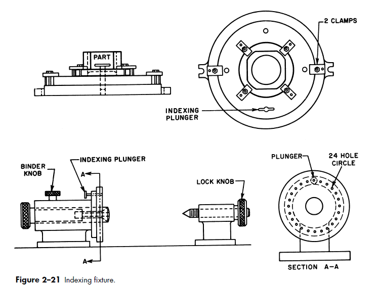
Indexing fixtures (fixtures) are very similar to indexing jigs
(Figure 2–21). These fixtures (fixtures) are used for machining
parts that must have machined details evenly spaced.


uses of an indexing fixture.
Multistation fixtures (fixtures) are used primarily for highspeed,
high-volume production runs, where the
machining cycle must be continuous. Duplex fixtures (fixtures)
are the simplest form of multistation fixture, using
only two stations (Figure 2–23). This form allows the
loading and unloading operations to be performed
while the machining operation is in progress. For
example, once the machining operation is complete at
station 1, the tool is revolved and the cycle is repeated
at station 2. At the same time, the part is unloaded at
station 1 and a fresh part is loaded.
Profiling fixtures (fixtures) are used to guide tools for
machining contours that the machine cannot normally
follow. These contours can be either internal or external.
Since the fixture continuously contacts the tool,
an incorrectly cut shape is almost impossible. The
operation in Figure 2–24 shows how the cam is accurately
cut by maintaining contact between the fixture
and the bearing on the milling cutter. This bearing is
an important part of the tool and must always be
used.


CLASSIFICATION OF FIXTURES
Fixtures (fixtures) are normally classified by the type of
machine on which they are used. Fixtures (fixtures) can also be
identified by a subclassification. For example, if a
fixture is designed to be used on a milling machine, it
is called a milling fixture. If the task it is intended to
perform is straddle milling, it is called a straddlemilling
fixture. The same principle applies to a lathe
fixture that is designed to machine radii. It is called a
lathe-radius fixture.


The following is a partial list of production operations
that use fixtures (fixtures):
Assembling Lapping
Boring Milling
Broaching Planing
Drilling Sawing
Forming Shaping
Gauging Stamping
Grinding Tapping
Heat treating Testing
Honing Turning
Inspecting Welding
SUMMARY
The following important concepts were presented in
this unit:
• Jigs and fixtures (fixtures) are production workholding
devices designed to hold, support, and locate a
workpiece.
– A jig guides the cutting tool with a drill bushing.
– A fixture references the cutting tool with a set
block and feeler, or thickness gauges.
• Jigs are divided into two general classes: drill jigs
and boring jigs. • The type of jig is determined by how it is built.
The two types of jigs are open and closed.
– Template, plate, table, sandwich, and angleplate
jigs are all open jigs.
– Box, channel, and leaf jigs are all closed jigs.
• Other variations, such as indexing, rotary, trunnion,
pump, and multistation jigs, are made as
either open or closed jigs.
• Fixture types are determined by the way they are
built. The most common types are plate, angleplate,
vise-jaw, indexing, and multistation fixtures (fixtures).
• Fixture classes are determined by the machine
tools on which they are used and sometimes by the
operations performed. A fixture used for a straddlemilling
operation is classed as a mill fixture, but it
may also be classed as a straddle-milling fixture.
REVIEW
1. What is the difference between a jig and a fixture?
2. How are jigs and fixtures (fixtures) normally identified?
3. What are set blocks used for?
4. What class of jig would normally be used to tap
holes?
5. A gang-milling fixture is actually what class of tool?
6. Analyze the following part drawings and operations
to be performed and select the best jig or
fixture for each.
A. Figure 2–25. Operation: Mill a slot .250 inch
by .250 inch.
1. Box fixture
2. Duplex fixture
3. Vise-jaw fixture

B. Figure 2–26. Operation: Drill four .500-inchdiameter
holes.
1. Plate jig
2. Angle-plate jig
3. Channel jig

C. Figure 2–27. Operation: Drill four holes (two
.62-inch and two .25-inch).
1. Channel jig
2. Plate jig
3. Box jig

D. Figure 2–28. Operation: Drill four holes, .50
inch in diameter.
1. Box jig
2. Angle-plate jig
3. Template jig

E. Figure 2–29. Operation: Mill a shoulder .75
inch by .75 inch by .38 inch.
1. Plate fixture
2. Angle-plate fixture
3. Indexing fixture

do you have answer for this review question?
ReplyDeleteJig manufacturing companies specialize in creating precise tools that guide the manufacturing process, ensuring accuracy and consistency. They play a key role in industries like aerospace, automotive, and electronics, providing customized solutions to improve production efficiency and reduce costs. jig manufacturing companies
ReplyDelete